
Solar power
MPPT Charger
Solar MPPT charger for 2S-4S lithium batteries
Charges a lithium battery from a solar panel and powers the site's load from the same DIN-rail module. It is built on the TI BQ25798 buck-boost charger with an ESP32-C3, and is set up and monitored from a web browser over Wi-Fi.
Available now. Online shop coming soon.
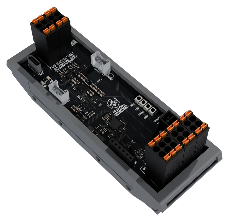
Overview
What it does
A second DC input takes over from the panel when a supply is available, and the load output stays up while the battery charges.
The factory setting suits the ModBee Battery Pack 18650: 3S, 12.6 V, 1.0 A.
The inputs have no reverse-polarity protection, so check the panel and supply polarity before connecting.
Features
- Maximum power point tracking for a 12 V nominal panel, up to 24 V open circuit, 3 A, 50 W
- Charges 2S-4S Li-ion, Li-Po and LiFePO4, 6-17 V, up to 3 A
- 3 A load output from the system rail, which stays up while the battery charges
- Second input for 5-24 V DC, used first when both inputs are present
- Battery temperature sensing (10 kΩ NTC) with JEITA charge limits
- Browser setup and monitoring over Wi-Fi
- RS485, two Grove I2C ports and a GPIO header for expansion
Views
Renders


Specifications
Technical details
Figures from the schematic, the module datasheets and the documentation on GitHub.
Documentation| Charger | TI BQ25798 buck-boost, 1.5 MHz |
|---|---|
| Processor | ESP32-C3, 160 MHz RISC-V, 4 MB flash, Wi-Fi 2.4 GHz |
| Solar input | 12 V nominal panel, Voc 24 V max, 3 A, 50 W |
| DC input | 5-24 V DC |
| Battery | 2S-4S Li-ion, Li-Po or LiFePO4, 6-17 V, charge current up to 3 A |
| Factory setting | 3S Li-Po, 12.6 V, 1.0 A |
| Load output | 3 A |
| Protection | TVS and snubbers on both inputs and on the battery and system rails; input over-voltage, battery over-voltage, thermal shutdown, charge safety timer |
| Interfaces | RS485, 2 x Grove I2C (3.3 V), GPIO header, USB-C |
| Mounting | 35 mm DIN rail enclosure, 118 x 42 x 45 mm |
Wiring
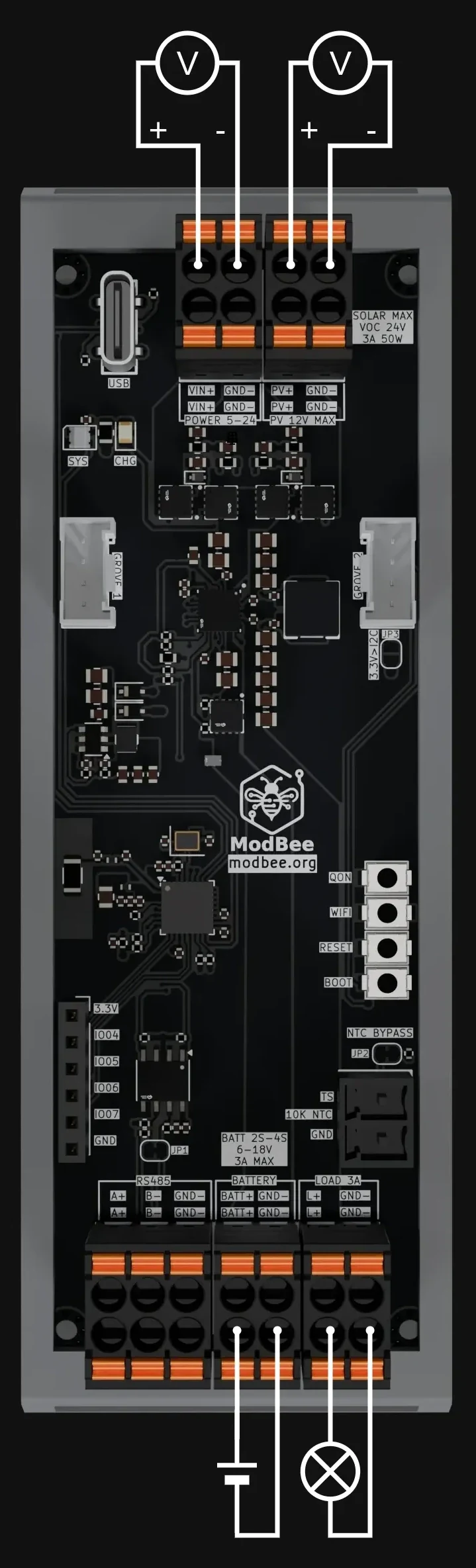
Terminals and connections
- Solar
- PV+ and GND. 12 V nominal panel, Voc 24 V max, 3 A, 50 W.
- DC input
- VIN+ and GND, 5-24 V DC. Used first when both inputs are present.
- Battery
- BATT+ and GND, 2S-4S lithium, 6-17 V, up to 3 A charge.
- Battery temperature
- TS, for a 10 kΩ NTC. A solder bridge bypasses it.
- Load
- L+ and GND, 3 A from the system rail.
- RS485
- A+ and B-, with 120 Ω termination by solder bridge.
Works with
Goes with
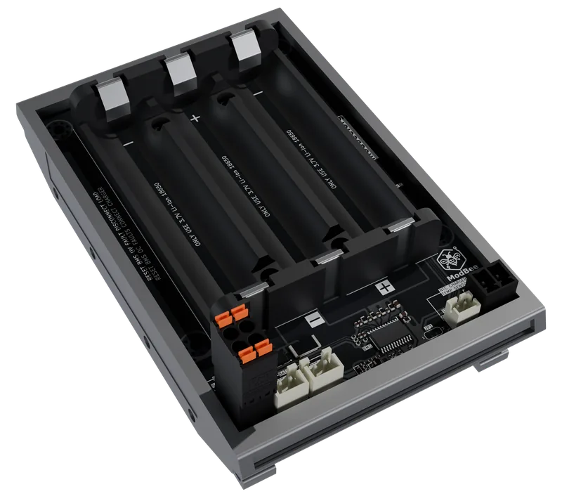
With the Battery Pack 18650, connect the pack's charger thermistor to the TS input and keep the charge current at 1.5 A or less.
Software
What runs it
Its own firmware is open on GitHub, written for the Arduino framework and built with PlatformIO. Setup and monitoring run from a web page served by the charger over its own Wi-Fi access point. Modbus RTU over RS485 is planned.
Downloads
Schematic and documents
Schematic
PDF, Rev 0.02, 372 KB
Connection diagram
Every terminal with example wiring
Documentation
Hardware notes and setup, on docs.modbee.org