
Controller
Node UIO
Industrial I/O controller for DIN rail
Node UIO is the controller at the centre of the ModBee range. It is built on the ESP32-S3 and has 8 digital inputs, 8 digital outputs, 4 analog inputs, 2 analog outputs and two RS485 ports on plug-in terminals. HATs stack on top to add cellular, LoRa mesh radio or a mains power supply.
Available now. Online shop coming soon.
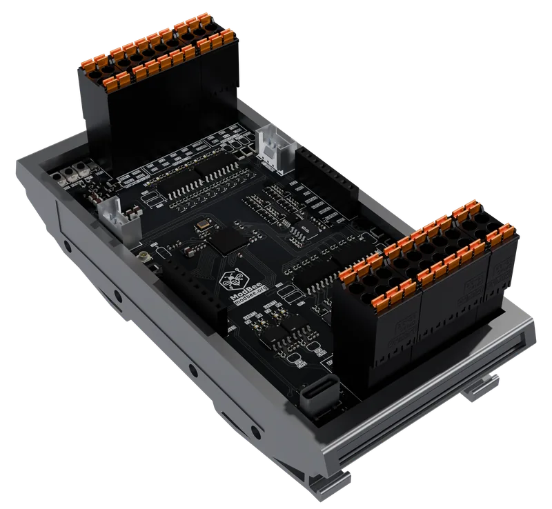
Overview
What it does
Program it in OpenPLC with ladder, function block diagram or structured text, or write your own firmware in Arduino or PlatformIO. ModBee libraries cover MQTT and Sparkplug B, Modbus, BeeBus, cellular and over-the-air updates.
Every input and output has its own LED, the terminals unplug for wiring, and solder bridges set the analog channels, RS485 termination and antenna without changing parts.
Features
- 8 opto-isolated digital inputs, 5-24 V DC, in two groups of four with separate commons
- Pulse counting on up to four inputs, and wake from deep sleep on any input
- 8 opto-isolated sourcing MOSFET outputs: 100 mA each, or 500 mA each from a separate output supply
- 4 analog inputs, 16-bit, 0-20 mA or 0-10 V per channel
- 2 analog outputs, 15-bit, 0-10 V or 0-20 mA per channel
- 2 RS485 ports with automatic direction control and selectable 120 Ω termination
- 2.4 GHz Wi-Fi on a chip antenna, or an external antenna on the U.FL connector by moving one solder bridge
- USB-C for programming, two Grove I2C ports, and LEDs on every input, output and RS485 line
Views
In the enclosure and on the bench


Specifications
Technical details
Figures from the Rev 0.01 schematic and the hardware notes. The full pin map and solder bridge settings are in the hardware notes on GitHub.
Hardware notes| Processor | ESP32-S3, dual-core 240 MHz, 512 KB SRAM, 4 MB flash, 2 MB PSRAM |
|---|---|
| Power supply | 5-24 V DC. The analog outputs need at least 9 V |
| Digital inputs | 8, opto-isolated, 5-24 V DC, 2 groups of 4 with separate commons |
| Digital outputs | 8, opto-isolated high-side MOSFET, 5-24 V, 100 mA each (500 mA with a separate supply) |
| Analog inputs | 4, 16-bit (ADS1115), 0-20 mA as shipped, 0-10 V by solder bridge, calibration stored on the board |
| Analog outputs | 2, 15-bit (GP8413), 0-10 V as shipped, 0-20 mA by solder bridge |
| Serial | 2 x RS485 (CH0 and CH1), half duplex, automatic direction, 120 Ω termination fitted, 1 kΩ fail-safe bias |
| Wireless | Wi-Fi 802.11 b/g/n, 2.4 GHz. Chip antenna as shipped, U.FL by solder bridge |
| Expansion | 2 stacking HAT headers, 2 Grove I2C ports (3.3 V) |
| USB | USB-C, native ESP32-S3 USB (serial and JTAG) |
| Protection | Resettable fuse, reverse-current diodes, USB ESD protection, clamped analog inputs |
| Indicators | RGB status LED, power LED, LEDs on every input, output and RS485 TX/RX line. Reset, Boot and Wi-Fi buttons |
| Terminals | Plug-in: power, digital in, digital out, analog in, analog out, RS485 |
| Mounting | 35 mm DIN rail enclosure, 118 x 58 x 45 mm |
Wiring
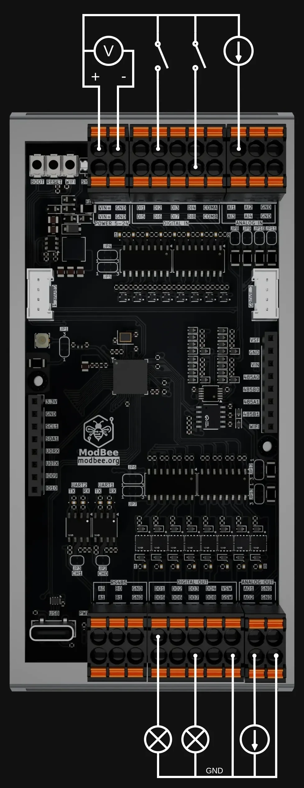
Terminals and connections
All terminals are plug-in, so the board can be wired before it goes in and swapped without rewiring.
- Power
- VIN+ and GND, 5-24 V DC. USB-C powers the logic only, for programming on the bench.
- Digital in
- DI1-DI8 with commons COMA and COMB. An energised input reads on.
- Digital out
- DO1-DO8, sourcing from VSW. Up to 500 mA each from a separate supply.
- Analog in
- AI1-AI4. 0-20 mA as shipped; 0-10 V per channel by cutting a solder bridge.
- Analog out
- AO1 and AO2. 0-10 V as shipped; 0-20 mA per channel by solder bridge.
- RS485
- CH0 and CH1, A and B, with 120 Ω termination fitted on each port.
Works with
Stack the HATs the site needs
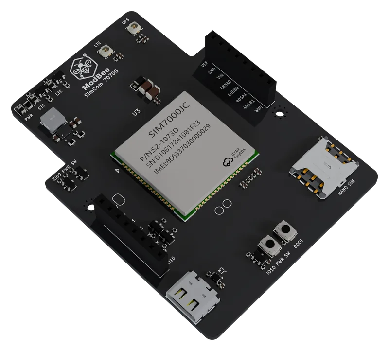
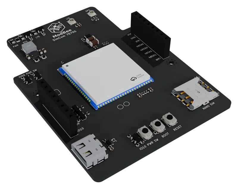
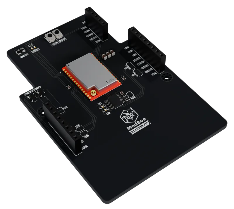
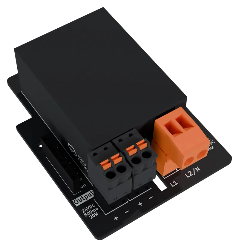
HATs plug onto two 8-pin headers carrying power, I2C, a UART and both RS485 pairs. Fit one cellular HAT per stack; the LoRa Mesh HAT can share a stack with it. For sites with no power, the MPPT Charger and Battery Pack run the Node UIO from solar.
Software
Program it in OpenPLC or Arduino
OpenPLC
Install the ModBee Node UIO board package in the OpenPLC Editor and pick ModBee Node UIO as the target. The I/O is read and written by function blocks: a UIO block runs first in every scan, then DIGITAL_IN, your logic, DIGITAL_OUT, ANALOG_IN and ANALOG_OUT. Programs can be written in ladder, function block diagram or structured text.
ModBee OpenPLC librariesArduino and PlatformIO
Add the ModBeeNodeUIO library to the Arduino IDE or PlatformIO, choose the LOLIN S3 Mini board with USB CDC on boot enabled. The library has functions for the inputs, outputs, analog channels, pulse counters and sleep modes. The optional NodeWebUI library adds a live I/O web page.
Node UIO library on GitHubThe same board runs the ModBee MQTT and Sparkplug B, Modbus, BeeBus, GSM and OTA libraries, in OpenPLC or in your own firmware.
Downloads
Schematic and documents
Schematic
PDF, Rev 0.01, 694 KB
Connection diagram
Every terminal with example wiring
Hardware notes
Pin map, solder bridges, power and protection
Library and examples
ModBeeNodeUIO for Arduino and PlatformIO